
Description and Requirements
The Book
Bibliography
Syllabus
 Introduction
The Great Pyramid
Music of the Spheres
Number Symbolism
Polygons and Tilings
The Platonic Solids
Roman Architecture
Number Symbolism in the Middle Ages
The Wheel of Fortune
Celestial Themes in Art
Origins of Perspective
What Shape Frame?
Piero della Francesca
Leonardo
Façade measurement by Trigonometry
Early Twentieth Century Art
Dynamic symmetry & The Spiral
The Geometric Art of M.C. Escher
Later Twentieth Century Geometry Art
Art and the Computer
Chaos & Fractals
Introduction
The Great Pyramid
Music of the Spheres
Number Symbolism
Polygons and Tilings
The Platonic Solids
Roman Architecture
Number Symbolism in the Middle Ages
The Wheel of Fortune
Celestial Themes in Art
Origins of Perspective
What Shape Frame?
Piero della Francesca
Leonardo
Façade measurement by Trigonometry
Early Twentieth Century Art
Dynamic symmetry & The Spiral
The Geometric Art of M.C. Escher
Later Twentieth Century Geometry Art
Art and the Computer
Chaos & Fractals

FAÇADE MEASUREMENT
BY TRIGONOMETRY
Figure: Surveying Exercise. From Fillipo Calandri, De arithmetica (Florence 1491). Baxandall p. 106
We are all familiar with the trigonometry textbook problem, "The angle of elevation to the top of a building from a point 200 feet from ... Find the height of the building," and such methods are hardly new. Here we describe a trigonometric method than not only measures heights of points on a building, but widths and depths of those points. It will give the height, horizontal position, and depth, (x, y, and z coordinates) of each selected point.
This method was developed for the purpose of measuring Medieval and Renaissance structures in Italy, for research in the history of architecture. To measure a building, a historian is most likely to use a tape measure from scaffolding set up for that purpose, a direct but costly and laborious method. This method provides a more accurate and less expensive alternative.
| Outline: | |
| Background | |
| The Method | |
| Derivation of Equations | |
| Field Test | |
| Measurements in Italy | |
| Summary |
Background
Figure: The radio astronomico used to measure the width of a façade. Frisius, 1545. From Kemp p. 169.
A literature search revealed few references to a trigonometric method. Martin Kemp, when talking about Fillipo Brunelleschi, the architect of the cupola of the Cathedral in Florence, says "On his first visit to Rome, as described in his biography, he made measured drawings of Roman buildings, using his understanding of standard surveying techniques 'to plot the elevations', using measurements 'from base to base' and simple calculations based on triangulation. The basis for such procedures would have been the 'abacus mathematics' he learnt as a boy." His source for this information is Antonio Manetti's Life of Brunelleschi." A search of Manetti's biography found reference to a visit to Rome, but no mention of his use of trigonometry to measure façades. In fact, there is some doubt expressed by the editor, Howard Saalman, that Brunelleschi ever went to Rome, and that this passage was added to enhance the stature of Manetti's subject.
Also according to Kemp, Leonardo recorded in the Codice Atlantico a cross-shaped measuring staff which he called the bacolo of Euclid, which was used to establish similar triangles. This instrument was perfected in the sixteenth century as the radio astronomico by the geographer and astronomer Gemma Frisius, who commends it for terrestrial as well as astronomical measurements.
Figure: An astrolabe used for surveying a building. From Cosimo Bartoli, Modo di misurare, Venice 1589. Kemp p. 168.
Kemp speaks of mediaeval instruments of considerable elaboration and precision, most notably quadrants and astrolabes, which could be used for terrestrial mensuration, although this was not their prime function. Cosimo Bartoli shows an astrolabe being used for the measurement of a building.
Figure: A compound bussola, from Bartoli. Kemp p. 170,
Raphael described a circular instrument used for his survey of ancient Rome, at the center of which is a compass, and a peripheral scale with arms that carry sight-vanes. A similar device called a bussola is described in Bartoli's book. The theodolite used for our present method is nothing but a more precise version of the bussola.
More recently, dimensioned drawings of façades have also been made by stereophotogrammatry, such as those for Independence Hall in Philadelphia. The Pantheon in Rome was surveyed by a method that used two electronic theodolites to simultaneously sight a point on the structure, their output being fed to a computer to give an instantaneous readout of coordinates.
The Method
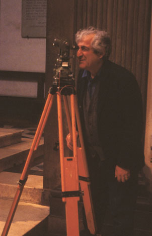
Slide 18-2: Theodolite Setup
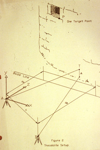
The equipment needed for this method is a surveyor's tape and a theodolite, an instrument for measurement of horizontal and vertical angles. It consists of a bubble level to establish the horizontal and vertical, a telescope that can rotate vertically in a mount that can also turn horizontally, with precise scales to read the angles.
To get the depth dimension, the procedure requires two theodolite setup positions, with a set of readings taken from each location. This second setup also provides a second set of numbers with which to check the first. This method will work with walls that are leaning out of plumb, have offsets, are curved, or have projecting elements like sills or cornices.
This procedure does not require the theodolite to be at the same height at each position, thus is suitable for sighting from sloping ground. Further, it is not required that the two theodolite positions be at the same distance from the wall.
The procedure will give two values for each y coordinate, which are independent and can be averaged to give a final value.
Procedure
- Study the façade. Take photos. Measure by manual taping whatever can be easily reached. Make a preliminary drawing. Choose and number the target points. Place adhesive targets on the wall, where possible.
- Select or lay out a base line. The intersection of the façade and pavement makes a good base line, if it is straight and horizontal. Use a stretched cord if no suitable physical base line is available, as shown in the figure. The figure shows what is possibly the most difficult measuring situation, a curved building on sloping ground. Mark two theodolite setup points A and B on the ground or pavement, which can be at different heights and at different distances from the base line. Record their horizontal distance c apart and their horizontal distances dA and dB to the base line.
- Set up and level the theodolite at location A. With the telescope horizontal, sight and mark a point T at any place on the wall also visible from location B.
- Set a plumb line over the other theodolite location. Sight the plumb line with the theodolite and adjust the horizontal scale of the theodolite to read zero.
- Sight each target. For each, record the horizontal angle a and the vertical angle q.
- After each target has been sighted, move the theodolite to the second location. With the telescope horizontal, sight a point R on the wall vertically in line with point T, found in step 3. Measure the vertical distance D from that point to T.
- Repeat steps 4 and 5, recording the horizontal angle b and the vertical angle n for each target point.
- Enter all measurements into the computer spreadsheet and print out the x, y, and z coordinate of each target point.
- Make a final dimensioned drawing by hand or by use of a CADD program.
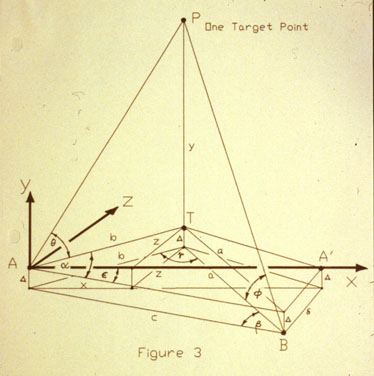
Slide 18-4: The Angles to be Measured
Derivation of Façade Equations
The equations that the spreadsheet uses to reduce the data are easily derived. Starting with the three original taped measurements,
c = Horizontal distance between theodolite locations.
dA and dB are the horizontal perpendicular distances from base line to theodolite locations.
D = Vertical offset between theodolites
From these we get
d = Horizontal offset = dB - dA
e = Angular offset = arcsin (d/c)
L = distance AA' between A & B parallel to baseline
=  c2 - d2
For each target P we have,
a = horizontal angle at A from B to target
q = vertical angle at A from horizontal to target
b = horizontal angle at B from A to target
f = vertical angle at B from horizontal to target.
Our coordinate axes will be as shown in the figures, with the origin at A, with the x axis parallel to the baseline and directed to the right, the y axis vertical and directed upwards, and the z axis perpendicular to the xand y axes, and directed towards the building. A simple translation of axes will later place the origin at any selected point, such as a corner of the building, and a rotation of axes can adjust the base line to be parallel to any selected line.
We now calculate the x coordinate of point P.
g = 180 - a - b
a = c sin a / sin g
b = c sin b / sin g
Figure: Plan View
From the plan view we see that
cos (a - e) = x / b
x = b cos (a - e)
Next we find the y coordinate of point P. From position A:
tan q = y / b
From position B:
y = b tan q
tan f = (y + D) / a
y = a tan f - D
As mentioned, the values of y found from each setup position are independent. Next we find the z coordinate of point P.
sin (a - e) = z / b
From which,
z = b sin (a - e)
Field Test
Figure: Green Academic Center
The method was tested by taking measurements of the front of Green Academic Center at Vermont Technical College. The figure shows eleven target points, all visible from both theodolite locations. These were sighted using a Wild T2 theodolite, capable of a precision of about 0.2 seconds of arc. The baselines were taped three times using a standard surveyor's tape graduated in millimeters, and the readings averaged. The data was reduced using a spreadsheet. Some of the distances measured by theodolite were also taped, for comparison.
A pair of values was obtained for each y coordinate, corresponding to the two equations used for their calculation. These, of course, should be identical for each target point, and their difference gives us some measure of the precision of the method. Here we found a deviation from their average value of less than 0.2%.
Comparing points that are expected to be at the same height on the building, or at the same depth, or on the same vertical, we found differences less than a few millimeters. These deviations may represent inaccuracies in the measurements, or may represent actual differences in height of these points.
On the basis of this one test, it would appear that, with moderate care, accuracies within a few centimeters, or within 2%, are easily obtained. There is no theoretical limit to the accuracy of the method.
Measurements in Italy
Torre Bernarda
Slide 18-6: Torre Bernarda
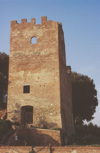
The first real use of the method was on the western façade of the Torre Bernarda, a Medieval tower in the town of Fucecchio, near Florence.
Slide 18-8: Sighting the Torre
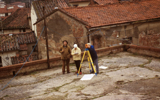
Since the terrain did not enable us to establish a base line parallel to the façade, a modified procedure was used. The same equations used before apply here, but with the horizontal offset and the angular offset both equal to zero. Then by a simple translation of axes, the origin was placed at a convenient point on the façade, and a rotation of axes put the x axis in the plane of the façade. Accuracies obtained were of the same order as for the VTC measurements.
Medici Chapel
Slide 18-10: Medici Chapel Interior
A second use for the method was measurement of the interior of Michelangelo's Medici Chapel in Florence. This was part of a project to deduce the systems of proportions Michelangelo may have used in its design.
Due to the darkness of the interior, we used a laser pointer to mark the approximate position of a measuring point, and illuminated that feature with a flashlight.
Laurentian Library
Figure: Entrance to the Laurentian Library, from the Vestibule
A third project was the doorway to the Laurentian Library in Florence, again to investigate what proportions Michelangelo may have used. Here the door is shown as seen from the vestibule, just outside the library itself.
Summary
In conclusion. we have here a fast, inexpensive, low-tech tool for measuring façades capable of giving accuracies of less than 1%, which, for good measure has roots firmly planted in the history of architecture.
Reading
Façade Measurement by Trigonometry. Paul Calter, from Nexus: Architecture and Mathematics, Kim Williams, editor, 1996.
Martin Kemp, The Science of Art. New Haven: Yale U. Press, 1990
